From Prototype to Production: Scalable IOL Moulding for Ophthalmic OEMs
This article outlines the technical workflows and quality systems required for the development and production of intraocular lens (IOL) tooling and moulded components, focusing on ultra-precision cavity design, high-performance polymer selection, cleanroom moulding integration, and compliance with global medical device standards. Intended for ophthalmic OEMs and engineering leads, this article addresses the practical challenges of scaling from R&D prototyping to validated, production-grade IOL moulding systems.
1. Optical Tooling Design for IOLs
The geometric fidelity of intraocular lenses directly affects optical performance and postoperative outcomes [1]. Tooling must enable replication of complex lens geometries—especially aspheric and toric profiles—with:
Sag height tolerances within ±0.25 µm
Surface roughness (Ra) below 10 nm to reduce stray light scatter
Form error (PV) less than 0.5 µm, measured via interferometry
No flow-induced birefringence or optical warping due to gating strategy or shear stress [2]
Tool steel selection (e.g., H13, S136, 420 SS) is driven by polishability, dimensional stability under thermal cycling, and compatibility with high-viscosity optical polymers such as PMMA or hydrophobic acrylics [3].
FEA and injection flow simulations are applied to validate: Filling dynamics (Moldex3D, Autodesk Moldflow), Thermal distribution and cooling asymmetries, Gate location effects on refractive index gradients.
2. Prototyping Tools and Iterative Development
For R&D and regulatory prototyping, single-cavity prototype tools allow rapid iteration of lens geometry, typically with interchangeable optical inserts.
Tooling specifications:
|
Feature |
Specification |
|
Insert surface finish |
<10 nm Ra, polished to SPI-A1 or better |
|
Optical geometry |
±0.25 µm form accuracy (aspheric/toric) |
| Gate design |
Submarine or edge gate with manual degating |
| Cleanroom rating |
Class 7 (ISO 14644-1) or better |
Metrology tools: Zygo interferometry for form error and surface roughness, Stylus profilometry for gate transition and edge inspection, Optical power mapping per ISO 11979-2:2014 [4].
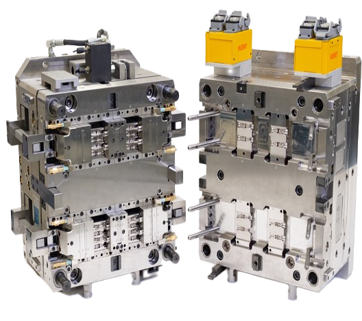
3. Multi-Cavity Production Tools
Production-scale moulds for IOLs typically range from 2–16 cavities. Key design concerns include:
Cavity-to-cavity repeatability (ΔRMS < ±0.2 µm)
Thermal balance (±2°C) across hot runner tips
Venting and vacuum assists to eliminate gas traps in edge features
Parting line and flash control within <25 µm total width [5]
Validated tooling typically includes: Integrated cavity pressure and temperature sensors (e.g., Priamus, Kistler), Electric or servo valve gating for consistent fill across all cavities, Conformal cooling for uniform shrinkage and cycle time reduction, Optical insert alignment using dowel pin or kinematic coupling systems.
4. Injection Moulding Environment and Process Validation
Injection moulding for IOL components is carried out in ISO Class 7 or 8 cleanrooms, using electric or hybrid presses for precision shot control. Polymer melt stability is critical to avoid yellowing, depolymerisation, or optical defects [6].
Process parameters typically include:
|
Parameter |
Typical Value |
|
Shot weight |
< 0.2 g |
|
Melt temperature |
220–250°C (PMMA) |
|
Mould temperature |
60–80°C |
|
V/P switchover |
Monitored to ±0.01s |
| Holding pressure decay |
Controlled over 0.5–2s |
Polymer drying is performed under <0.02% moisture content (Karl Fischer titration), as per ISO 11357-6 for PMMA and cyclic olefin copolymers [7].
Validation steps include: IQ/OQ/PQ protocols following ISO 13485:2016, Traceability via lot-level process data and sensor logging, In-line vision inspection with defect detection <25 µm.
5. Post-Moulding Metrology and Optical Testing
Intraocular lenses require strict dimensional and optical characterisation:
Wavefront and power mapping: Shack-Hartmann sensors and MTF measurement [8]
Surface roughness (Ra): Atomic Force Microscopy (AFM) or laser confocal scanning
Refractive power tolerance: Within ±0.25 D as per EN ISO 11979-2
Flash and gate remnant inspection: Vision system with 3σ validation capability
Critical-to-function features (CTQs) are linked to cavity master data. Automated feedback loops allow insert refurbishment before wear-induced form drift occurs.
6. Tooling Lifecycle and Refurbishment
High-volume IOL tools (>1M cycles) are designed for: Modular insert replacement, Wear-resistant coatings: DLC, CrN for demoulding and polish longevity, Predictive maintenance intervals based on cavity pressure deviation or shot count thresholds.
Tooling logs include cavity history, polish cycles, sensor drift, and coating integrity—aligned with ISO 14971 risk management traceability.

Scalable IOL moulding requires integration of precision optical tooling, cleanroom-grade injection systems, and ISO-compliant process controls. For OEMs, early-stage involvement with toolmakers familiar with ophthalmic geometries and regulatory validation is essential. From pilot tools to high-cavity production systems, a structured, metrology-driven approach ensures optical performance, yield efficiency, and long-term compliance.
References
- Werner, L. (2009). “Intraocular lens optics and design: past, present, and future.” EyeNet Journal, AAO.
- Riedel, N., & Kuth, R. (2016). “Injection moulding of optical components: Material effects on birefringence.” Journal of Polymer Engineering.
- Guillon, M. et al. (2014). “Tool steel selection for optical inserts.” Precision Engineering, 38(4), 734–741.
- ISO 11979-2:2014. “Ophthalmic implants – Intraocular lenses – Part 2: Optical properties and test methods.”
- Polymer Processing Institute (2020). “Mould venting techniques for micro optical moulding.”
- Speranza, V. et al. (2015). “Thermal degradation of PMMA: Kinetics and influence of processing.” Polymer Degradation and Stability, 112, 160–165.
- ISO 11357-6:2018. “Differential scanning calorimetry – Part 6: Determination of oxidation induction time (isothermal OIT) and oxidation induction temperature (dynamic OIT).”
- Artal, P. (2009). “Image formation in the human eye and optical quality.” Journal of Vision, 9(3):6.