Common Injection Moulding defects
Numerous factors influence the quality of plastic injection-moulded parts, usually including the mould tool and its inserts’ design, process and finish, material choice, quality control during the moulding process, and more. Injection moulding mistakes or mistakes resulting from the materials utilised in the process might be quite expensive for the manufacturers. The final product may include flaws ranging from minor, surface-level quality faults to more significant ones that could compromise the product’s efficacy and safety.
Therefore, in order to lower the likelihood of potential injection moulding faults, it’s critical to adopt a proactive approach to risk mitigation throughout the product development process.
Flow lines
On thinner sections of moulded components, flow lines emerge as a wavy pattern that is frequently coloured differently from the surrounding area. They may also show up on a product’s surface as ring-shaped bands close to the mould’s “gates.” Component integrity is unaffected by flow markers. When wearing expensive sunglasses, they might be ugly and uncomfortable.
Causes:
Variations in the rate at which the melted plastic cools as it passes through the heated barrel and mould and solidifies are what result in flow lines. As the material cools at varying rates, this also occurs if there are thick and thin walls rather than uniform wall thickness.
- Machine: Insufficient injection pressure. Too little time. Too little heat is present in the barrel. The temperature of the nozzle is too low. Erratic cycle time
Solutions:
- Boost the material’s temperature, injection pressure, and speed to guarantee that it fills the mould before cooling.
- Curve the mould’s corners where the wall thickness increases to help maintain a constant flow velocity and avoid flow lines.
- Mould coolant should be kept farther away from mould gates in order to assist prevent the material from cooling too quickly during flow.
- To increase flow rate and avoid premature cooling, enlarge the nozzle diameter.
Burn marks
Burn marks are discolourations on the surface or edges of the finished plastic product. Typically, their hue is either dark brown or rust. Burn markings from injection moulding generally don’t compromise the integrity of the item, but they can lower the final product’s visual quality.
Causes: Burn marks are typically caused by trapped air or overheating plastic in the heated barrel or nozzle, which leads to burn marks in the finished product.
- Machine: Too high injection speed, pressure, screw speed, barrel temperature. Nozzle temperature is too high and diameter is too small.
- Mould: Inappropriate size and location of venting and gating.
- Material: Too low flow. Excessive lubricant and regrind use.
Solutions:
- Reduce the temperature of the melt and mould to avoid overheating.
- To lessen the chance of air becoming trapped inside the mould, lower the injection speed.
- Expand gas gates and valves to let trapped air out of the mould
- Reduce the mould cycle time to prevent resin and trapped air from overheating.
Vacuum voids
Air pockets inside a moulded plastic object are known as plastic injection moulding voids. Void sections are hollow areas that can affect shape, fit, and function by compromising the final product’s structural integrity and appearance. Since voids are located beneath a part’s surface, users typically won’t notice one until the part breaks, unless it’s transparent or water-clear.
Causes: Low injection pressure, inadequate venting, or resin tainted by moisture are the causes of these spaces. One of the most frequent injection moulding flaws in parts with thick walls is air pockets.
- Machine: Too low injection pressure and forward time. Too high injection temperature. Lack of material feed. Injection speed is too high. Not enough back pressure.
- Mould: Inappropriate venting, runners, gates. Too low mould temperature.
- Material: Too high moisture.
- Design: Thick walls.
Solutions:
- Put more force into the injection to expel any trapped air pockets.
- Select a material grade with reduced viscosity to minimise the possibility of air bubble formation.
- To avoid premature cooling where the material is most susceptible to voids, place gates in close proximity to the thickest portions of the mould.
Warping
Warping is a prevalent flaw in injection moulding, which occurs when the moulded plastic component deforms or changes shape after cooling and solidifying. The term “warping” refers to the distortion, twisting, or bending of a part, which might cause it to fit or perform incorrectly. Semi-crystalline materials are more prone to warping.
Causes: Two parts of the moulded product have variable melt cooling rates, which results in warpage.
- Machine: Insufficient injection time or pressure. Too little time spent there. Too little heat is present in the barrel. The temperature of the nozzle is too low. Insufficient cycle time. Underpacking – inadequate cushioning. An excessive amount of tension.
- Mould: Too low a mould temperature. Too-small runners or gates. Inappropriate gate location. Inconsistent moulding temperature irregular ejection
- Material: Inaccurate rate of flow
- Design: Thick wall.
Solutions: It’s important to make sure that injection-moulded components cool down sufficiently gradually to avoid internal tensions that could damage the item, which will help prevent warpage defects. The most significant benefit of uniform wall thickness in mould design is that it helps guarantee that plastic flows through the mould chamber in a single direction.
- In order to shorten the cooling period, lower the melt temperature.
- As directed, bring the mould temperature down to a manageable range.
- If there is any pressure loss, raise the pack and hold pressures.
- Extend the pack and hold durations.
- Warpage results from inadequate cooling time following ejection. To ensure that the part cools down sufficiently, extend the cooling period.
Sink marks
Sink marks are tiny indentations or depressions in an injected-moulded part’s otherwise smooth surface. Overly thick wall sections are frequently the source of sink marks because the molten plastic inside the section pulls material inside as it cools more slowly, creating a visible flaw. Sink marks can be especially harmful to premium goods that need to have a flawless finish.
Causes: The main cause of sink marks is an overly sluggish cooling rate of molten plastic. This is not like other flaws, which are more frequent because the plastic cools down too quickly. Materials that take too long to cool can develop sink marks because the shrinkage that results pulls the material inward before it has had time to cool to take on its final shape.
- Machine: Too much heat in the barrel. Inadequate time or pressure during injection. Not enough time to cool down. Brief hold and cushion duration. Faulty check valve
- Mould: Too high of a mould temperature at the junctions and opposite ribs. Too-small gates or runners. Incorrect gate placement. Overly long gate land. Trapped gases or air. An uneven flow pattern
- Material: Too coarse or excessive regrind use
- Design: Thick walls
Solutions:
- In order to give the material close to the part’s surface more time to cool, increase holding pressure.
- To reduce shrinkage, extend the cooling period.
- Create a mould with thinner component walls so that the area near the surface may cool more quickly.
Jetting
An uneven solidification process can also lead to jetting problems in injection moulding. When a first jet of resin enters the mould and has time to start setting before the cavity fills, this is known as jetting. This weakens the portion and leaves visible, squiggly flow patterns on the surface of the piece.
Causes:
When a molten material “jet” hardens before the hole is filled, it causes jetting, a distortion of the moulded component. Jetting, which often originates from the injection gate, appears as a squiggly line on the completed component. Visible flow could make a part less strong.
- Machine: Injection speed is too high. Inappropriate barrel temperature. Inappropriate nozzle opening (too small) and nozzle temperature.
- Mould: Low mould temperature. Too small gates or runners. Incorrect gate location and gate length.
- Material: Inappropriate flow rate
Solutions:
- Lowering the injection pressure to stop the material from squirting into the mould cavity too quickly
- Raising the material and mould temperature will prevent the material’s first jet from hardening too soon.
- Arranging the injection gate in the mould’s design so that the material is directed across it as opposed to longitudinally.
- Increase the size of the gate to increase material flow.
Weld lines
Where the molten material has converged after splitting off into two or more directions in a mould, welding lines may show up on the surface of the moulded object. Weak material bonding causes the hair-like weld line, which reduces the part’s strength.
Causes: When molten material or polymer fronts collide, a certain temperature must be maintained. If not, they partially solidify and are unable to bind well enough, leading to weld lines.
- Machine: Too low barrel temperature. Too low injection pressure and speed.
- Mould: Too low mould temperature. Too small gates and runners.
- Material: Inappropriate flow rate.
Solutions:
- Raise the temperature of the substance to avoid partial solidification.
- Increase the pressure and pace of the injection to prevent cooling before the material fills the mould.
- Modify the mould to remove dividers
- To facilitate faster flow and avoid premature cooling, switch to a material with a lower melting temperature or viscosity.
Discolouration
When a moulded object turns out to be a different colour than anticipated, it is called discoloration, or “colour streaking.” Frequently, the deterioration on a moulded item is restricted to a small area or a few aberrant colour streaks. Usually, this flaw compromises the part’s strength but alters its appearance.
Causes: A number of things can lead to discolouration, such as the resin becoming contaminated by moisture or other foreign substances, being overheated, or being exposed to ultraviolet (UV) light. Discolouration may also result by using pigments or colourants that are unsuitable.
- Machine: Too high shot size ratio and residence time. Too high barrel and nozzle temperature. Inconsistent cycle time.
- Mould: Inappropriate mould temperature, cooling and venting.
- Material: Contaminated material.
Solutions:
- In order to remove any leftover pellets or base material, make sure that employees thoroughly clean the hopper, nozzle, and mould in between production runs.
- Clean the machine using a purging agent to get rid of extra colour.
- Make that the colour agent you or your supplier is using has enough heat stability.
- To ensure a consistent colour output, make sure the master batch is mixed equally.
Short shot
Short shots are pieces that are imperfect and unusable because the resin does not completely fill the mould hole. Fork prongs missing or plastic shelves partially assembled could show up in a short shot. Short shots are a serious flaw that can affect how well an item works or looks.
Causes: The majority of short shots result from blocked or narrow gates that restrict flow. Filling a material before it cools down is only occasionally feasible when it is excessively cold or dense. It’s possible for air pockets to impede flow, and injection pressure may be low.
- Machine: Inadequate feed material. Too little heat is present in the barrel. Faulty check ring. Not enough pressure on the back. Too little of a nozzle and insufficient injection pressure or speed. Not enough time for the injection. Overindulgent feed cushion. Excessive clearance of the non-return valve. Creating a bridge in the feed throat. Inadequate press capability
- Mould: Too low a mould temperature. Too-small gates or runners. Incorrect gate location. Not enough time to vent. The runner diameter is too narrow and the sprue bushing is excessively lengthy. Too little sprue diameter
- Material: Incorrect rate of flow. Overindulgence in regrind. Use of excessively coarse regrind and high moisture content. Irregular granule size
- Design: Thin wall. Complex features.
Solutions:
- Extend channels or gates to improve the flow of mould.
- To improve flow, increase the base material thickness, injection pressure, or speed.
- To slow down the cooling of the material, raise the mould’s temperature.
- Mould vents should be added or extended to release trapped air.
Surface delamination
In injection moulding, surface delamination is the result of thin layers on the polymer surface that readily come away or peel off. This phenomenon, known as delamination, is identified by a flaking surface layer. A severe injection moulding flaw is surface delamination, which considerably reduces the finished component’s strength.
Causes: Surface delamination typically happens when foreign particles, such as sheet metal, contaminate the basic materials. Another reason for surface delamination could be moisture on the material’s surface from improper drying before use.
- Machine: Too little injection speed is being used. Insufficient injection cushion. The injection hold duration is insufficient. Too little heat is present in the barrel.
- Mould: Too low of a mould temperature. Gate and runner corners are sharp. Overexposure to mould release.
- Material: Usage of very coarse regrind. Additives and foreign substances in the material. Overabundance of wetness.
Solutions: The resin must be free of impurities, and the moulding process parameters (temperature, pressure, injection speed, and cooling rate) must be properly adjusted and regulated to avoid delamitation.
- Raising the temperature in the mould.
- By appropriately pre-drying the material, any excess moisture is removed.
- Make sure employees handle and store the plastic with the utmost caution to prevent the cross-contamination of various polymers.
- Redesigning the mould with the injection nozzle as the main emphasis reduces the need for release agents.
- In order to lessen abrupt changes in the direction of the mould flow, smooth out the corners and twists in the mould design.
- In order to minimise the need for mould release agents—which may lead to contamination—the ejection mechanism should be given special consideration in the mould design.
Flash
When surplus material exits the mould cavity and creates a thin, undesired protrusion along the separating line or other shut-off places, it is referred to as flashing in injection moulding. The overall quality of the moulded product may be harmed by flashing, necessitating additional steps or post-production trimming to address the problem.
Causes: When there is too much material or pressure inside the mould, or when the mould is not properly closed or clamped, flashing may occur.
- Machine: Overly high injection pressure. Too much heat in the barrel. Overly long cycle time. Not enough clamp pressure.
- Mould: Inappropriate split line seal, mould supports and venting.
- Material: Too much mould lubricant.
- Design: Parting lines positioned at complex joints.
Solutions:
- If the plates don’t fit together correctly or the material is flowing outside the channel, retool or rebuild the mould.
- To restrict material flow to the channel, increase the clamping tension on the plates.
- To enhance material flow, modify the injection pressure, mould temperature, and ventilation.
Product stuck in mould
When a product is moulded, it typically adheres to the moving portion of the mould and is extracted with ejector pins when the mould is opened. If it doesn’t, it can result in ejector pin breakage.
Causes:
- Machine: Too high residual pressure.
- Mould: Irregular angle of the mould finish. Inappropriate size of mould draft.
Solutions:
- Reducing the pressure and temperature settings may aid in freeing the final product from its sticky situation.
- This could be avoided by making the mould draft larger or by reworking the mould to have a better finish.
- Mould parting agents are occasionally utilised.
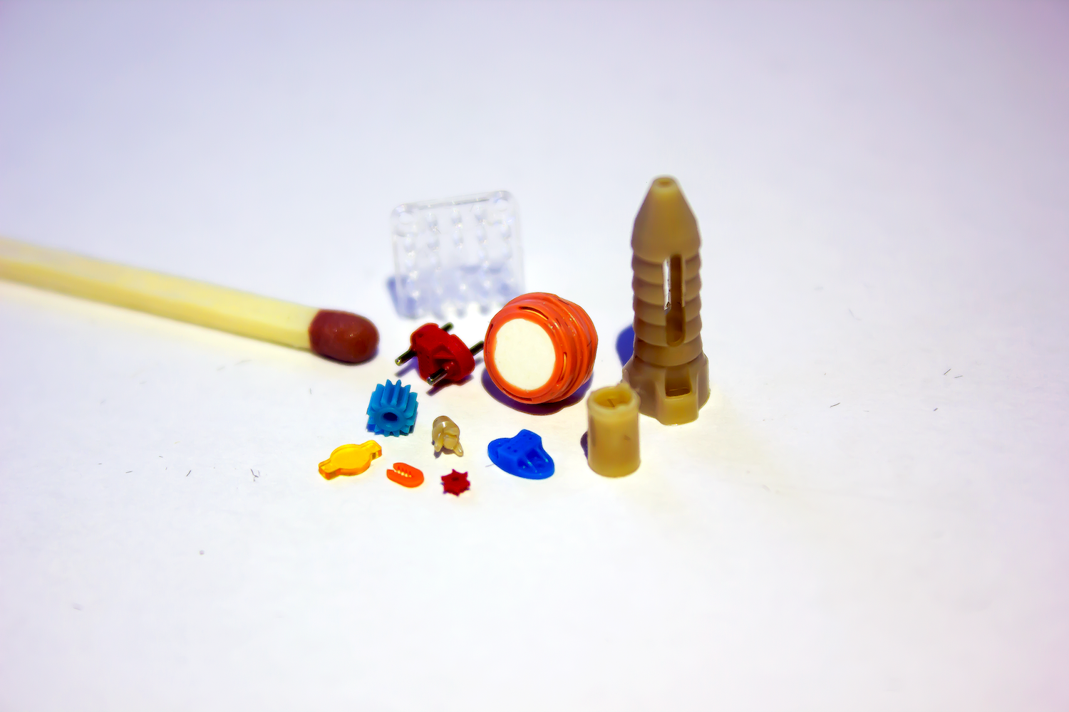
Micro moulded parts manufactured at Micro Systems
As with many processes, injection moulding can be a very effective manufacturing technique for creating highly reproducible plastic parts, but creating high-quality final products necessitates close attention to detail and aggressive risk management. In order to guarantee that products satisfy the highest quality requirements and stay clear of these frequent plastic injection moulding problems, everyone participating in the product development process—from the first design and proof-of-concept phases all the way through fulfilment—needs to exercise due diligence.
When designing and manufacturing any product for our clients, Micro Systems places a high value on accuracy and quality. Our quality control procedures begin with the first stages of design and continue through the manufacturing process, packaging, and delivery of your completed product. With more than 20 years of experience in the mould tool and moulding industry, our team of experts will collaborate with you to optimise the product design as well as the moulding procedure and mould to preserve form, fit, and function while proactively lowering the risk of defects.
Contact us today to discuss your mould tooling and injection moulding process!